Reader Note: This is a grown-up discussion about my years-long pursuit of the Perfect Ham Antenna. It actually relates closely to our usual Sunday ShopTalk format because building a serious ham radio antenna is as much about the execution of construction plans (and parameters) as it is about the underlying electronics.
Point being? If you are not a ham radio operator yourself (yet) you likely know one who can fill in the missing pieces. If not? I’ll take this one step at a time so you can follow along. I assure you – once you read this article sequence – you will know more about antenna theory than even a lot of hams.
Since I am writing a book on ham radio restoration and design of different things, I decided to share this chapter on antennas. Not that you will ever need to build a high-performance antenna, but it’s better to have more knowledge than you need in all aspects of life.
Wire Antennas & Wave Lengths
Simple wire antennas of the sort we’re dealing with come in two flavors. Resonant and non-resonant. Wm of the Radio Ranch is fond of saying “Magic happens at resonance.” It’s a useful generalization, though not perfect.
Radio frequencies come in wavelengths. 468 divided by the frequency in megahertz (MHz) will give you the HALF wave length in feet of any given frequency. Two such quarter wavelength wires – back-to-back and fed in the middle – comprise a dipole.
Let’s begin with the middle of the 80-meter ham band. Since it begins at 3.5 MHz and runs up to 4.0 MHz (e.g. 500 KHz wide), the middle point for a basic dipole discussion is half of the 500 KHz – so 250 KHz – added to the lower side (3.5 MHz), lands us at 3.75 MHz as the middle of the band.
Since a HALF wave pencils out (468/3.75) t0 124.8 feet, each quarter wave should be 62.4 feet.
The typical feedline used for antennas is called coaxial – coax (co-axe), for short – and it’s a center conductor, insulation around that, and then a shield wrapped around that and then more insulation.
Imagine a pipe – with a wire in the middle of it – then insulated. That’s the basic idea of something called “hardline.” Coax – rather than solid copper pipe – does the same thing, but is flexible.
This “wire with insulation” within “wire within insulation” means a special kind of connect has become common: Coax Connectors. You may have seen the small version of these. They’re typically used for small signal applications. Such as the cable TV line coming in from the street.
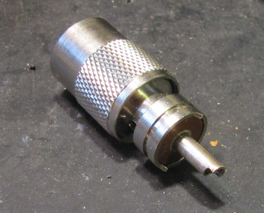
The special cable plugs used for handling transmitter power are usually different than the consumer cable TV fittings.
The most common for ham radio is probably the “UHF style” called a PL-259. The connector shown at right unscrews and the barrel (the upper/knurled part) is placed on the coax first. Then, insulation and shielding is stripped off and the plug is soldered on (though crimp styles are also available). Just remember that a PL is a PLug.
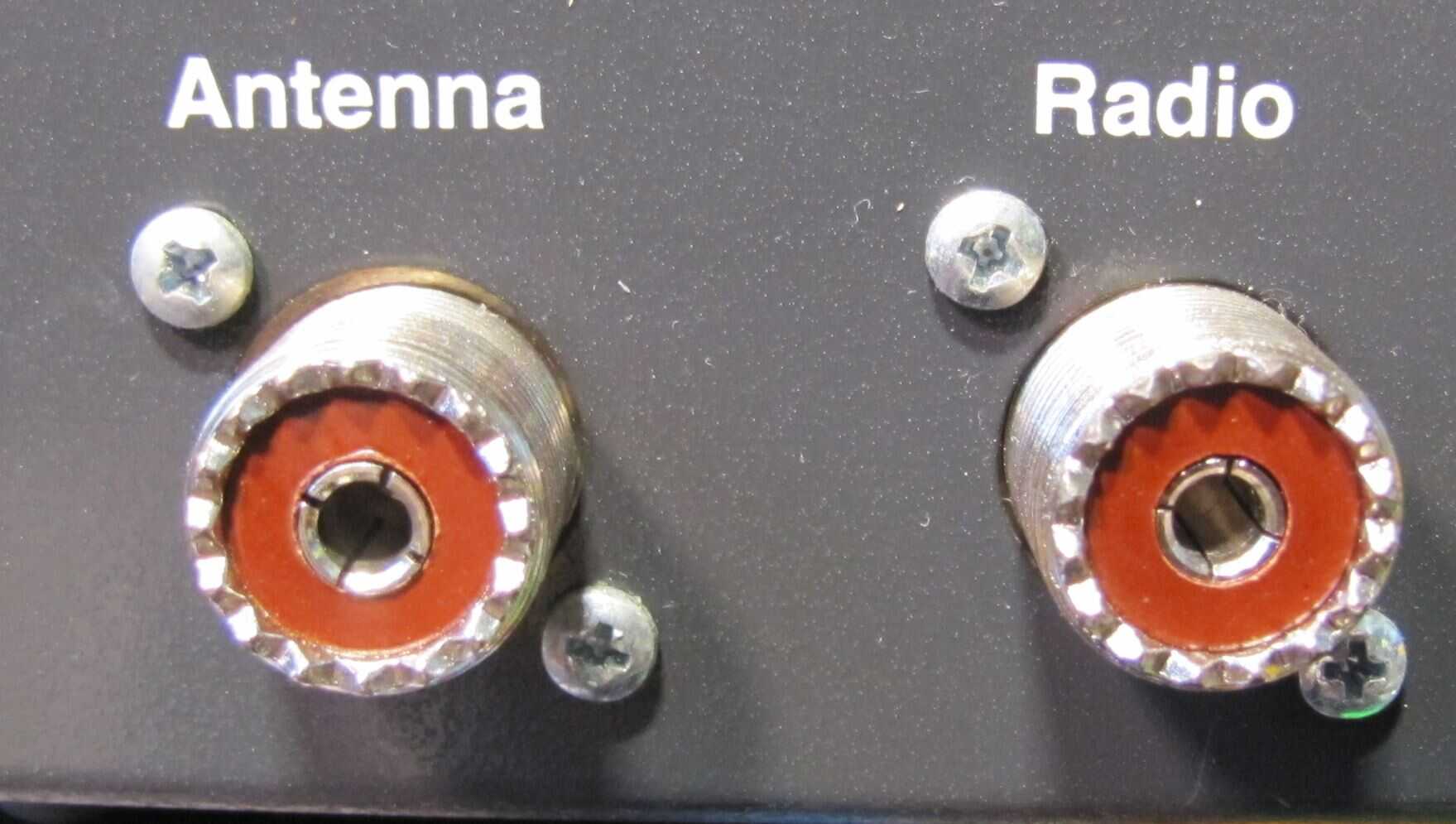 There’s another connector called an SO-239 that the PL-259 screws into. Whether on an antenna center insulator, or here as on the back of a receiver tuning unit called a Preselector. Just remember SO means SOcket and you’ll never be confused.
A similar coax connector type is called “N-connectors” and is mainly found on commercial and collectible Collins brand equipment. More difficult but a bit less loss, but that depends on frequency. The higher, the more losses in connectors, anyway.
Coax is good stuff. Like so many things in life though, the more expensive, the better. A cheap unbranded cable may only cost a dime per foot. But, super high quality Times Microwave cable (like LMR-400) can (with PL-259s installed) retail for more than $2 per foot. It doesn’t take long to pencil out some real savings by learning to make all your own cables and attachments.
Coax or Open Wire Line?
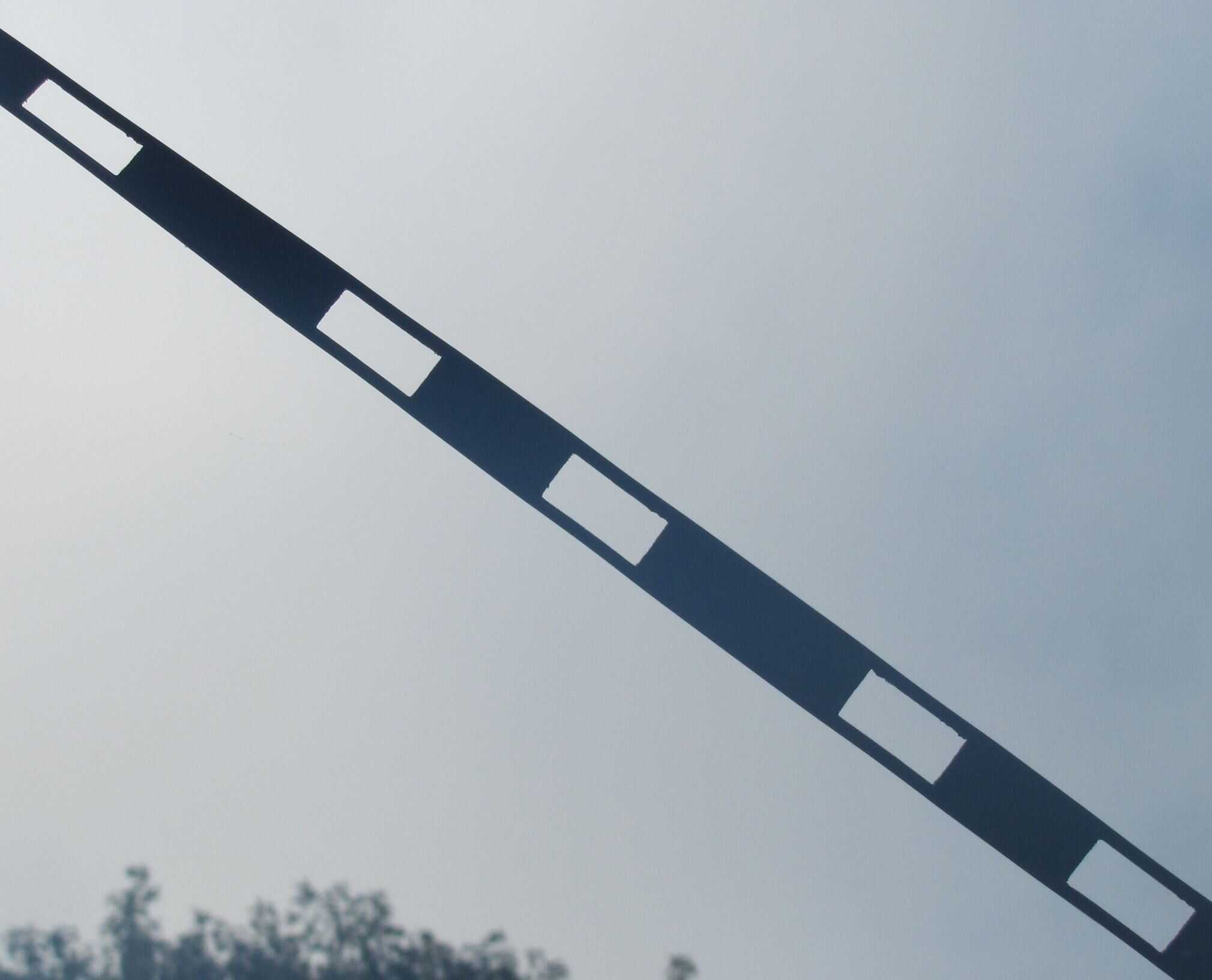 There is another kind of feedline used with antennas: Open wire and a variant called Ladder Line. It looks like this – the wires are about an inch and a half apart.
Since we live in East Texas where lightning can, at times strike almost daily in the spring, open wire or Ladder Line is very easy to handle from a safety standpoint.
On a coaxial cable, remember the ground (or cold) side of the outer shield goes to ground. While most coaxial cable switches figure lightning issues to be addressed when the center conductor is ALSO grounded, I’ve never been entirely happy with that idea. Lightning is Big Stuff.
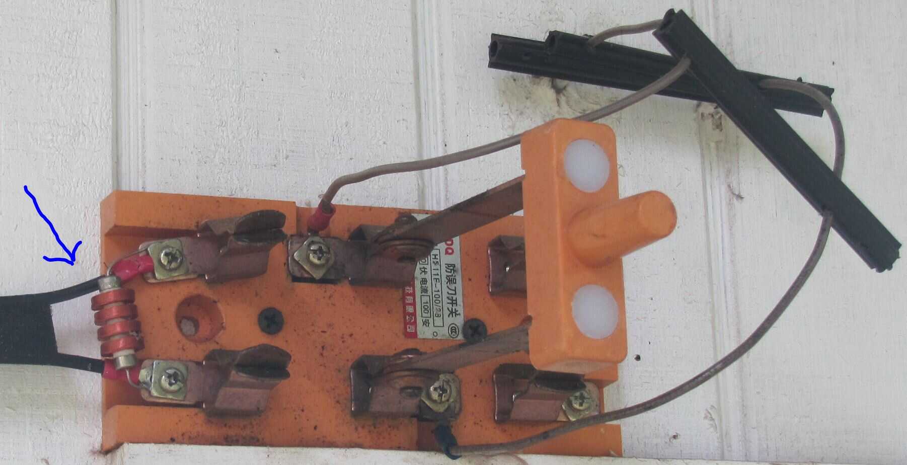 Using open wire or Ladder Line, it’s a simple matter of “throwing the Big Switch” which cost $23 and 10-days shipping from China on eBay.
On the left side, you’ll see there is a small device called an RF (for radio frequency) choke. It provides a D.C. connection between both sides of any antenna that happens to be hanging up on my tower for whatever hare-brained experiments I have going. Because it is a series of inductive wire bobbins (this is called a “four pie choke”) the radio signals are not shorted. Just lightning and local noise impulses.
This kind of local noise called “common mode noise” can reduce antenna performance more on receive than transmit. It arises when a local noise source (such as our big solar panel MPPT charge controllers) make power. The local noise radiated can be substantially reduced with radio frequency chokes.
Feedline Tradeoffs
So attention needs to be paid before designing an antenna to what type of feedline you’re planning to use. This is because certain antennas will ONLY perform well with one antenna type, or another.
Coax: There are lots of reasons to go with the crowd. The connectors are pretty robust. The cabling can be close to metal objects and doesn’t care because the signal is inside.
However! Downsides are that a) there is a higher loss rate for coax depending on something called standing wave ratio (we’ll get into that in a sec.). b) Common mode noise is on one side of the antenna feed, so grounding in many places becomes a new sport. And I don’t trust grounding switches any further than I can throw them. (“Give me big air gaps!”)
Open Wire Case: Massively cheaper and with negligible losses. Easy to totally disconnect when thunderstorms show up. The losses of open wire line can be the merest fraction of coax losses.
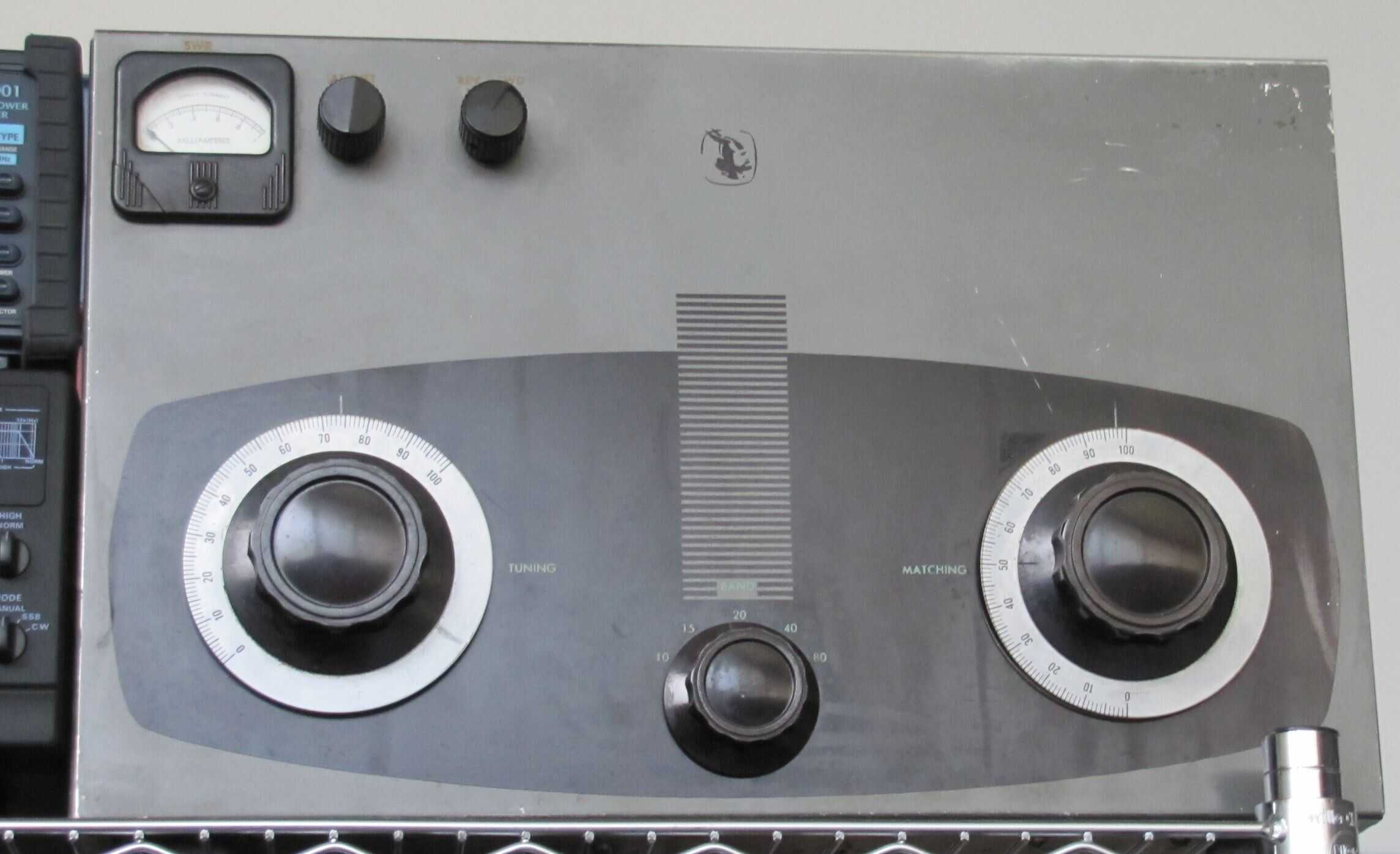 Sadly: No free lunch. Open wire line requires a real antenna tuner. This behemoth is one of two Johnson Match Boxes I own. Although I have a couple of others including a 3 KW MFJ, the Johnson is totally an old school great. They were designed to use 300 to 450 ohm impedance open wire and ladder lines at high power levels.
There’s a small (cheaper on the used market) version of the Matchbox which will handle 275 watts of AM. Since AM at 100 percent modulation has a peak envelope power of four times carrier, the smaller Matchbox will handle 1,100 watts PEP. The grown-up one will handle AT LEAST 4,000 watts PEP – well north of the FCC’s 1,500 watt PEP transmitter output limit.
We’re almost to our first antenna model. Hang in there.
Impedance Basics
If you have hung in this far, you maybe have an idea that “Impedance is sort of life Resistance.”
Let’s dig in a bit.
The basic rules of Resistance are spelt out in Ohm’s Law. It summarizes the relationship between voltage (E for electromotive force), current (I which only makes sense if you have the old-time ham radio decoder ring that reveals (I) originates from the French phrase intensité du courant, (current intensity). And R, of course, is Resistance in Ohms.
There are only two formulas that will handle maybe 60% of all electronic calculations: One is the Voltage equals Resistance times Current (E = i*r)
Example: 12 ohm (r) light bulb and 1 ampere of current (i) means a 12 volt (e) source is out there powering things.
The other is Power equals Voltage times Current (P = i*e).
Example: My big linear amplifier has 2,500 volts on the plate circuit of the output tube (e) and it’s drawing 0.4 amps when transmitting (* which is 400 milliamps where 1 milliamp is one-thousandth of an amp (thus 400-thousandths of an amp). So power P in watts is 2500*.4 or 1,000 watts.
Important NOTE; If you are running high power, don’t forget in your linear to add-back your driving power if you’re running grounded-grid. 1,000 watts with 85-watts driving would be construed as 1,085 watts by the FCC. This SEEMS like minutia now, but when we get into the extremes of performance we’ll get into in part two of this discussion – which includes Part 65 OET EMI exposure limits – little details like added back drive power really do matter.
Standing Wave Ratios
The output of more transmitters is normally measured as “so many watts” – which is the power output. And at “such-and-such” an impedance.
Since most “modern” transmitters are designed for coaxial cable (50 and occasionally 72 ohm impedance) the antenna should be closely “matched” to the transmitter output.
If it’s no, an antenna mismatch is present and a “standing wave” develops on the transmission line (typically coax cable).
If the antenna has an impedance of 100 ohms at the desired operating frequency, and the transmitter is happiest when feeding a 50-ohm antenna, the standing wave is said to be 2 to 1. If the antenna impedance is higher – say 150 ohms – then the standing wave is higher as a result. In this example 3 to 1.
Standing waves represent loss. Measured by “return loss.” In the case of our 100 ohm antenna and 50 ohm transmitter, the “return loss” is 10 decibels, which means (*simplifying a good bit) that 90 percent of the transmit signal will be radiated. The other 10 percent is called “reflected power” which bounces back and reradiates, but with additive losses.
Key: You want a low standing wave ratio and high return loss figure. The lower the SWR and the higher the return loss, the better.
“What is Impedance!!??“
Just getting to that: Now that you know how basic power transfers and how SWR and return loss works, remember this: Impedance is just a complex resistance!
“Complex?” you’re wondering. Well, PURE resistance is just that – resistance. Opposition to energy flow.
However, a complex resistance includes – in addition to resistance some reactance. Follow this carefully: Resistance PLUS a reactance is impedance differs.
There are two kinds of Reactance. One is Inductive Reactance (the result of a coil effects) while the other is Capacitive Reactance (as plates of a capacitor that store energy).
Impedance is designated by the letter Z (standing for a complex impedance). It’s relation to R (resistance) is defined by its reactive component jX. Simple formula here: Z = R + jX
EEPower.com has a dandy further discussion but this is enough to get started with. Except it helps to know that –j is capacitive and +j is inductive, but you won’t need to know that for a l o n g time.
Even if you’re NOT a ham radio geek (yet), this still applies in your consumer life. You see, when we get into alternating (house) current, the amount of reactance in an A.C. supply from your power company defines how much actual work is done by the power you’re paying for!
This is called the “Power Factor” of alternating current. Ideally, in a sine wave, the peak of the voltage coming in peaks at the same time the current peaks. If the voltage and current arrive exactly out of phase (180-degrees) then the power factor approaches zero.
In high voltage distribution systems for utilities, power factor is a HUGE deal. Because you can be paying, say 100% for your power. But you may only be getting 70% power factor…in which case time for a come to Jesus with the power company.
It’s also how those “miracle money savers” work. They are typically nothing more than a Capacitor designed to counteract Inductance – typically raising power factors. Which get screwed up with switch-mode power supplies. Like the ones used in your computers and televisions.
High and Low Z Antennas
Funny short technology story: Now that you know high and low impedances and what they are, a note on the evolution of antennas is not often spoken of but it’s instructive.
“Back in the day” a typical ham radio used tubes. These were high impedance devices because high voltages and low currents were involved. My first radio had about 600 volts and the typical plate current (final amplifier tube) was 100 milliamps or 0.1 Amp. Plate resistance? E/I = R (substituting from E=I*R, right?) So 600/.1 was 6,000 ohms.
This 6,000 number was very useful because – knowing there was 60 watts of radio energy, and that it takes half the radio energy as audio to modulate AM 100% (nice and loud, not quite distorting) you needed a 30-watt audio amplifier with a 6,000 ohm secondary modulation transformer!
OK, flashback there. But here’s the point: If the final amplifier tube has a 6,000 ohm plate resistance, the smaller the conversion ratio from amplifier to antenna, the lower losses would be.
This is why – in the era when 6,000 ohm plate resistance was common, the 10:1 transformation to a 600 ohm antenna was so popular. Hence great energy transfer. As the Pi-network output became popular, the 100:1 transformation worked, but it was more “particular.”
Transistors Changed Antennas
Now let’s see what happened in the 1970s when all-transistor ham radios started to appear.
With no high voltage on the plate, the E (voltage) in the transistor radio dropped to typically 12 volts. Current went through the roof! On voice peaks, 20 Amps was common to get 100 watts out. Remember, transistors of yore were not much more efficient than tubes. But they didn’t need a high voltage supply and they didn’t need filaments (also called heaters). Without those big transformers,, the radios output per pound zoomed!
And antenna impedances dropped. Again E was 12 volts and I was 22 amps. .54 Ohms.
We have to do a 100 to 1 up-conversion with inductors and capacitors to hit a 50-ohm antenna impedance which is not uncommon.
SO we then find ourselves with radios with built-in antenna tuners.
One thing led to another – transistors owned it – and the arrival of the bandpass filter – then the evolution of Chebyshev filters – ensured that low impedance antennas would rule the modern airwaves.
What Makes a Killer Antenna?
What we so far know is?
Some basic understanding of resistance versus impedance. A little history on impedance and radio design. Plus we get some ideas on what will make an antenna “play” well. High return loss!
Let’s fire up EZ-NEC and get to work on our simple dipole project and model it for one frequency. We’re sure to learn something.
Basic Dipole Model
Since we know the wire lengths involved, modeling this dipole is very simple.
First step is to plug in the two wires and give them a source at the center which will be our feedpoint. We’ll use a 50 tower and 50 trees.

Not sure how well acquainted you are with Cartesian ordinates?
In this model (varies with my mood) the x axis is left-right. The y axis is front to back. Which leaves the Z axis up and down with 0 being the ground. 50 foot tower and trees.
Wire #1 then is in the center of the model and 50 feet up. And from there comes towards us 62.4 feet. Wire #2 has the same origin point but goes away from us 62.4 feet. Both ends are 50-feet up.
SWR Discussion
We can now do a scan to see if this dipole we just built has a resonance (indicated by an SWR dip) somewhere around 3.75 MHz. Prepare to look carefully:
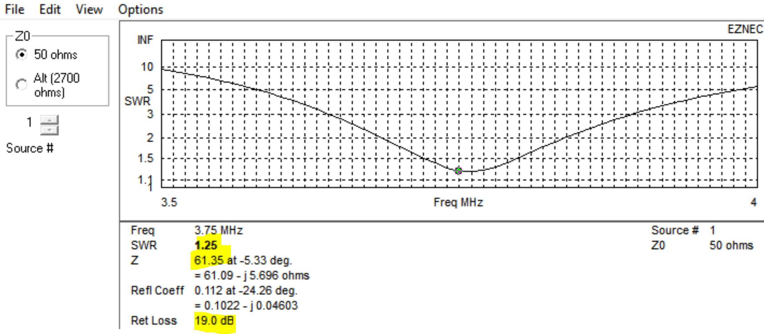
See where the yellow highlights are? The nominal standing wave ratio (minor impedance mismatch between our feedline (50 ohms) and the antennas (61.35 ohms) is about 1.25 to 1.
The Return Loss is 19.0 dB. Which means when we transmit something, 98.7% is leaving the antenna initially. Reference table buried in here somewhere…
We can use an antenna tuner to adjust the “match” – lowering the SWR and conversely raising the return loss, but the difference is barely noticeable in real life.
Lobes and Take-Off Angles
The next step modeling is to look at how the 3D pattern of our radiation looks.
While a dipole SHOULD have lobes perpendicular to the wires (a figure 8 that’s fat) we don’t see this because this antenna is less than a quarter wavelength off the ground.
So another criteria (besides a killer SWR and Return Loss figure) would be antenna gain over your ground and at the elevation you’re using.

The highlight at the bottom says the ideal antenna would have slight gain, but with the ground we’re using at the height, the Model Has Loss flag is on and there’s a small amount of overall loss.
Which we can understand a bit more when we look at the side view (called elevation):
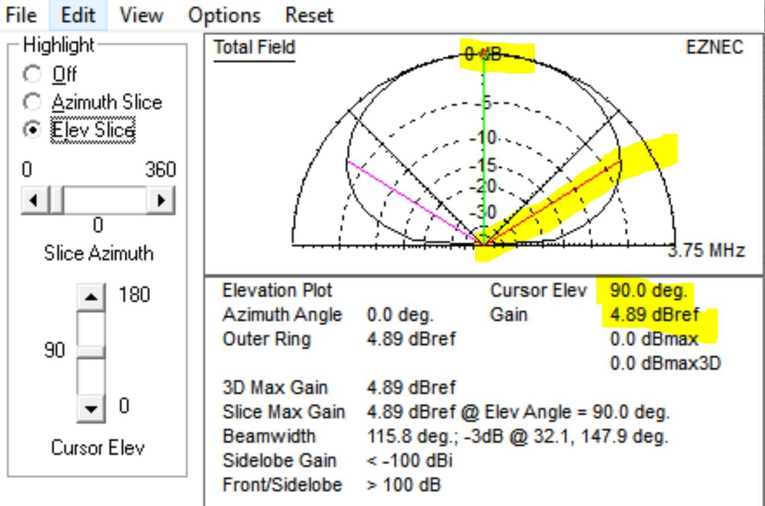
What this claims is that we actually have SOME gain when taking off at 35-degrees above the horizon. In fact, this is a perfectly workable antenna.
Seen from overhead, though, it has no directionality, though:
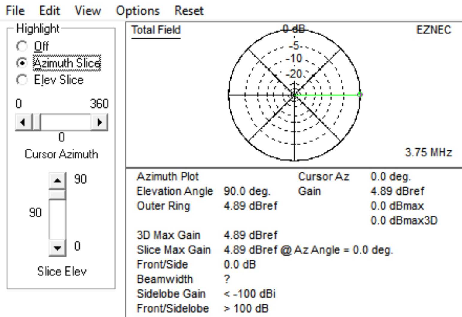
In real life applications, you can tweak with the directionality a bit. Biggest improvement would be to put the antenna a full wavelength up in the sky because at 250 feet,. those directional lobes I was mentioning would begin to appear. Let me show you….

The only problems with this antenna become apparent when we priced out a 240 foot tower (and aircraft lighting) and erection (and grounding) costs.
Elaine would hear nothing of it despite being a ham herself (KG4YHv).
Maybe if I work on her to upgrade to the next higher class license…
Ideal Antenna Design List
Going through this simple antenna introduction will give you some of the basics for understanding our fall antenna project this year.
First let’s look at the ideal antenna by band:
- 80-meters: 3.5-4 MHz. Daytime, we would like to have as much vertical take-0ff angle as possible in order to utilize NVIS (near-vertical incident skywave) propagation. The SWR should be low and the return loss as high as possible. We would like to see at least 3db of gain relative to a total field number of the dipole. Additionally, we’d like some serious take-off gain as close to vertical (90-degrees) as possible. Our starting point is -0.69 dB.
- 40-meters: 7.0-7.3 MHz. Anything is good here: However, 90 degree NVIS antennas are not so good at night on 40, but mostly my use for this band is rag chewing (chewing the fat, rat killing if you’re from 5 land). I can live with anything from 90 vertical down to 10 degrees, but around 45 degrees would be good. Better if installed the orientation would give me a major lobe to the north or northwest. Not just to talk with the Major but also to work some CW into Japan and the Western Pacific.
- 20-meters: 14.0-14.35 MHz. Magic here would be as much gain over a dipole as possible and in a cloverleaf pattern. The original SuperAntenna has about 9.5 dBref (decibels reference a dipole, 2.15 db) at 20-degrees take-off. In this iteration, though, there are two further deal points: FCC power limitations and low receiver noise.
Enter Part 65
The FCC has become much more interested in limiting RF exposure. And in their Part 65 they lay out all kinds of rules.
Yes, even on the lower ham bands now, it is easy to “bump up” against legal limits.
Let’s look as a sample exposure calculation on the upper end of 20-meters for a very good wire antenna:
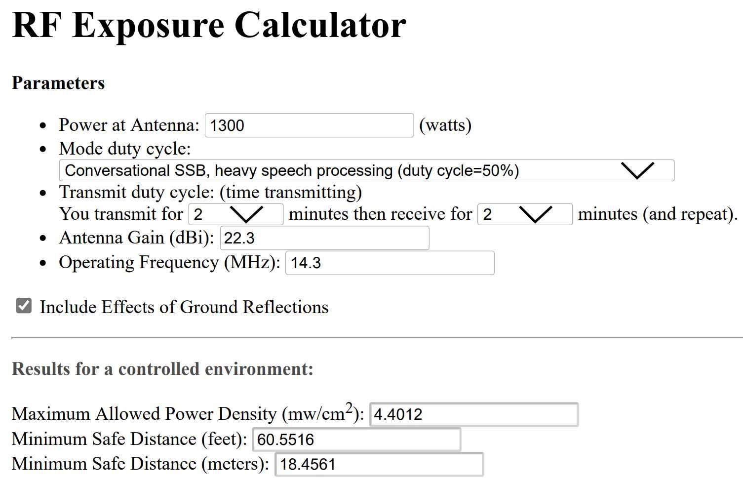
One of the reasons we live on 29-acres is so that I don’t have to mess with uncontrolled area exposures. The property is posted both no trespassing *(along with no hunting) and as a Controlled Area for RF access control.
Even so, you’ll see that the antenna (which we will get to in Part 2) has certain iterations that may result in exceeding FCC limits even 50-feet up.
As a practical matter, we don’t want to even get close to the limits on 20 meters because when we go up to 15-meters, we would almost certainly be out of tolerance, especially if the antenna had acceptable return loss/SWR numbers and sufficient maximum lobe gain.
Which gets me to the wrap-up point here:
The final engineering consideration is it doesn’t make a lot of sense to use some of my recently developed “tricks and treachery of antenna design” if you can get 36 dBi of gain, but then lose 20 dBi back in losses.
As we’ll see in the next part of this report, once the losses in a model become too large, the marginal rate of improvement for additional investments in copper and “altitude holders” (250 foot tower, anyone?) can quickly wash out.
Part 2 of this will be up Sunday.
Write when you get rich and QRQ
George@Ure.net /ac7x

Hank’s claim to have a high gain directional antenna the size of a bowling ball is the one I am waiting to see final the design on. Maybe you can convince Hank to publish his results .
No worries… I will publish it. And I’m sure George will, too. Sorry for the delays, but I am occupied with family care matters for awhile, but I am really itching to get it done. I will leave ‘those who think they know’ with an outrageous statement:
“Electromagnetic Waves do not propagate”. Stay tuned for the explanation.
OMG, did Clif tell ya they were vaxxed ?? Or do they have a delta-T > six weeks ?… naw, that’s just in Texas.
LOL, couldn’t leave that hangin’… but you’ve got my attention, Hank ! I’ll be curiously waiting. But, fer sure, spend that time with your Dad. The last 50 days with mine were priceless as he continued what he defined as his “data dump”.